An Introduction to IC4017
Most of us are more comfortable with 1, 2, 3, 4… rather than 001, 010, 011, 100. We mean to say that we will need a decimal coded output in many cases rather than a raw binary output. We have many counter ICs available but most of them produce binary data as an output. We will again need to process that output by using decoders or any other circuitry to make it usable for our application in most of the cases.
Let us now introduce you a new IC named IC 4017. It is a CMOS decade counter cum decoder circuit which can work out of the box for most of our low range counting applications. It can count from zero to ten and its outputs are decoded. This saves a lot of board space and time required to build our circuits when our application demands using a counter followed by a decoder IC. This IC also simplifies the design and makes debugging easy.
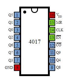

It has 16 pins and the functionality of each pin is explained as follows:
- Pin-1: It is the output 5. It goes high when the counter reads 5 counts.
- Pin-2: It is the output 1. It goes high when the counter reads 0 counts.
- Pin-3: It is the output 0. It goes high when the counter reads 0 counts.
- Pin-4: It is the output 2. It goes high when the counter reads 2 counts.
- Pin-5: It is the output 6. It goes high when the counter reads 6 counts.
- Pin-6: It is the output 7. It goes high when the counter reads 7 counts.
- Pin-7: It is the output 3. It goes high when the counter reads 3 counts.
- Pin-8: It is the Ground pin which should be connected to a LOW voltage (0V).
- Pin-9: It is the output 8. It goes high when the counter reads 8 counts.
- Pin-10: It is the output 4. It goes high when the counter reads 4 counts.
- Pin-11: It is the output 9. It goes high when the counter reads 9 counts.
- Pin-12: This is divided by 10 output which is used to cascade the IC with another counter so as to enable counting greater than the range supported by a single IC 4017. By cascading with another 4017 IC, we can count up to 20 numbers. We can increase and increase the range of counting by cascading it with more and more IC 4017s. Each additional cascaded IC will increase the counting range by 10. However, it is not advisable to cascade more than 3 ICs as it may reduce the reliability of the count due to the occurrence glitches. If you need a counting range more than twenty or thirty, I advise you to go with conventional procedure of using a binary counter followed by a corresponding decoder.
- Pin-13: This pin is the disable pin. In normal mode of operation, this is connected to ground or logic LOW voltage. If this pin is connected to logic HIGH voltage, then the circuit will stop receiving pulses and so it will not advance the count irrespective of number of pulses received from the clock.
- Pin-14: This pin is the clock input. This is the pin from where we need to give the input clock pulses to the IC in order to advance the count. The count advances on the rising edge of the clock.
- Pin-15: This is the reset pin which should be kept LOW for normal operation. If you need to reset the IC, then you can connect this pin to HIGH voltage.
- Pin-16: This is the power supply (Vcc) pin. This should be given a HIGH voltage of 3V to 15V for the IC to function.
This IC is very useful and also user friendly. To use the IC, just connect it according the specifications described above in the pin configuration and give the pulses you need to count to the pin-14 of the IC. Then you can collect the outputs at the output pins. When the count is zero, Pin-3 is HIGH. When the count is 1, Pin-2 is HIGH and so on as described above.
Application of CD4017
LED Sequencer using 4017
The LED sequencer circuit by using CD4017 and IC 555 is shown below. This circuit is also called as “LED chaser circuit”.
Components
- CD4017 decade counter
- 555 timer IC
- Ten-segment bar graph LED
- switch and One 6 volt battery
- 1 MΩ resistor
- 0.1 µF capacitor
- Coupling capacitor, 0.047 to 0.001 µF
- 470 Ω resistors-10
Primarily it is important to remember that, as the CD4017 is a CMOS device, it is very sensitive to the static electricity.

The LED sequencer circuit uses the 555 timer to produce the clock pulses required for CD4017, which is operated in Astable mode. Output of this Astable timer circuit is connected to the clock signal input of CD4017.
It produces stream of pulses continuously, in which the each pulse increases the counter by 1. So thus each LED will light up and then off before turning on its next LED in the sequence.
LED sequencer working
- Led sequencer works on the principle of CD4017.
- Let us understand the working by starting with 555 timer.
- 555 timer is operated in astable mode.It produces clock pulses continuously to the decoder IC.The duration of this clock pulse can be calculated by using R and C value in the circuit.
- For each pulse the CD4017 increases the counter value.Thus each pin of the counter goes high in a sequence.
- LEds connected to the output pins of CD4017 ,thus glows in a sequence.
Note
In order to make the counter to count upto certain number ,the last sequence pin should be connected to reset.
No comments:
Post a Comment